Example Drawings: Difference between revisions
GavinWootton (talk | contribs) No edit summary |
|||
| (35 intermediate revisions by 4 users not shown) | |||
| Line 9: | Line 9: | ||
File format: | File format: | ||
[[File:MediaWiki Example Image Format.PNG|frameless|300px]] | [[File:MediaWiki Example Image Format.PNG|frameless|300px]] | ||
=Document Manager Layout= | |||
In the document manager there are certain ways drawings are named in the title 1 column. | |||
*Design Intent - DI | |||
*Production Drawings - PD | |||
*Installation Drawings - ID | |||
*Fabrication Drawings - FD | |||
*Rolled Drawings - RD | |||
These are titled by 'Prefix' 'number' | |||
For example a PD title page would be titled "PD 0". This is so that the first stanchion will be titled "PD 1". | |||
These prefix's are added so that any drafter can load into a model and sort by title 1 and the drawings will be listed accordingly. | |||
=Basic Drawing Layout Guide= | =Basic Drawing Layout Guide= | ||
| Line 37: | Line 54: | ||
Design intent title pages should include | Design intent title pages should include | ||
*An overall isometric view of the model | *An overall isometric view of the model | ||
*Product details (inc, type, finish, colour, balustrade dia, fixings) | *Product details (inc, type, finish, colour, pipe OD, balustrade dia, fixings) | ||
* | *Special notes | ||
*Customer name | |||
*Project name | |||
*Job number | |||
*Any required revision notes | |||
*Initials | |||
*Dates | |||
[[File:DI_Title.PNG|frameless|950px]] | [[File:DI_Title.PNG|frameless|950px]] | ||
| Line 46: | Line 69: | ||
<div class="toccolours mw-collapsible" style="width:950px; border:none; background-color:transparent; overflow:auto;"> | <div class="toccolours mw-collapsible" style="width:950px; border:none; background-color:transparent; overflow:auto;"> | ||
<div class="mw-collapsible-content"> | <div class="mw-collapsible-content"> | ||
PD, FAB, and rolled title pages should include | |||
*An overall isometric view of the model | |||
*BOM list | |||
*Customer name | |||
*Project name | |||
*Job number | |||
*Any required revision notes | |||
*Initials | |||
*Dates | |||
[[File:PD_FAB_Rolled_Title.PNG|frameless|950px]] | [[File:PD_FAB_Rolled_Title.PNG|frameless|950px]] | ||
</div></div> | </div></div> | ||
| Line 52: | Line 85: | ||
<div class="toccolours mw-collapsible" style="width:950px; border:none; background-color:transparent; overflow:auto;"> | <div class="toccolours mw-collapsible" style="width:950px; border:none; background-color:transparent; overflow:auto;"> | ||
<div class="mw-collapsible-content"> | <div class="mw-collapsible-content"> | ||
Install drawing title pages only need bubbles if the BOM is small enough to fit all part bubbles in the title page. | Install title pages should include | ||
*An overall isometric view of the model | |||
*BOM list | |||
*Installation QR code | |||
*Customer name | |||
*Project name | |||
*Job number | |||
*Any required revision notes | |||
*Initials | |||
*Dates | |||
Note: Install drawing title pages only need bubbles if the BOM is small enough to fit all part bubbles in the title page. | |||
If the title looks too busy, remove the bubbles and give them separate pages. | If the title looks too busy, remove the bubbles and give them separate pages. | ||
| Line 62: | Line 107: | ||
<div class="toccolours mw-collapsible" style="width:950px; border:none; background-color:transparent; overflow:auto;"> | <div class="toccolours mw-collapsible" style="width:950px; border:none; background-color:transparent; overflow:auto;"> | ||
<div class="mw-collapsible-content"> | <div class="mw-collapsible-content"> | ||
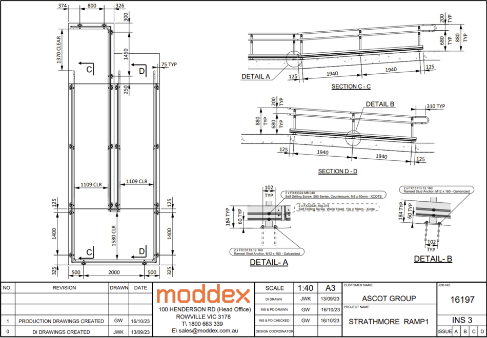
This is a general disability ramp layout. | |||
A few things to note: | |||
*All stanchions are equal length apart | |||
*Stanchions are placed 125mm from the ramp edges | |||
*Detail views of both flat and angled baseplates | |||
[[File:Disability Ramp INS.PNG|frameless|950px]] | [[File:Disability Ramp INS.PNG|frameless|950px]] | ||
| Line 67: | Line 119: | ||
==Small Stair== | ==Small Stair== | ||
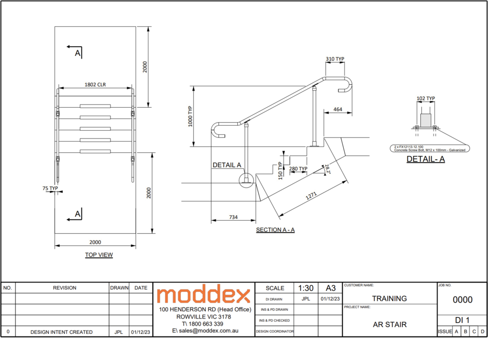
This is the general layout of a small staircase. | |||
Couple of things to note: | |||
*Measurements show the angle, nosing to nosing, rise, and run lengths | |||
*Measurements showing how far both bottom landing and top landing closures stick out | |||
On more simpler designs, try to show more information to fill out the page. | |||
There is a lot of space to fill, so show the customer a bit more information than what's just necessary. | |||
[[File:Small Stair DI.PNG|frameless|950px]] | [[File:Small Stair DI.PNG|frameless|950px]] | ||
| Line 72: | Line 135: | ||
<div class="toccolours mw-collapsible" style="width:950px; border:none; background-color:transparent; overflow:auto;"> | <div class="toccolours mw-collapsible" style="width:950px; border:none; background-color:transparent; overflow:auto;"> | ||
<div class="mw-collapsible-content"> | <div class="mw-collapsible-content"> | ||
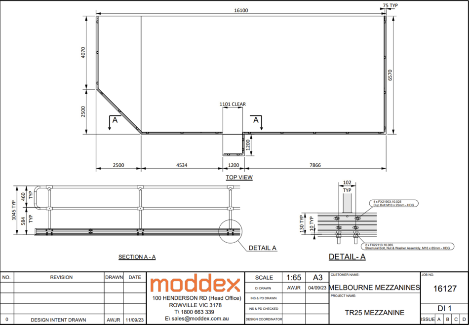
Mezanines are usually a simple top-down view. However, if there are more complex items in the model make sure they are shown in a section view. Items like this may include but aren't limited to gates, specific termination of pipe, complex bends and welded items. | |||
[[File:Mez_DI.PNG|frameless|950px]] | [[File:Mez_DI.PNG|frameless|950px]] | ||
| Line 92: | Line 156: | ||
<div class="mw-collapsible-content"> | <div class="mw-collapsible-content"> | ||
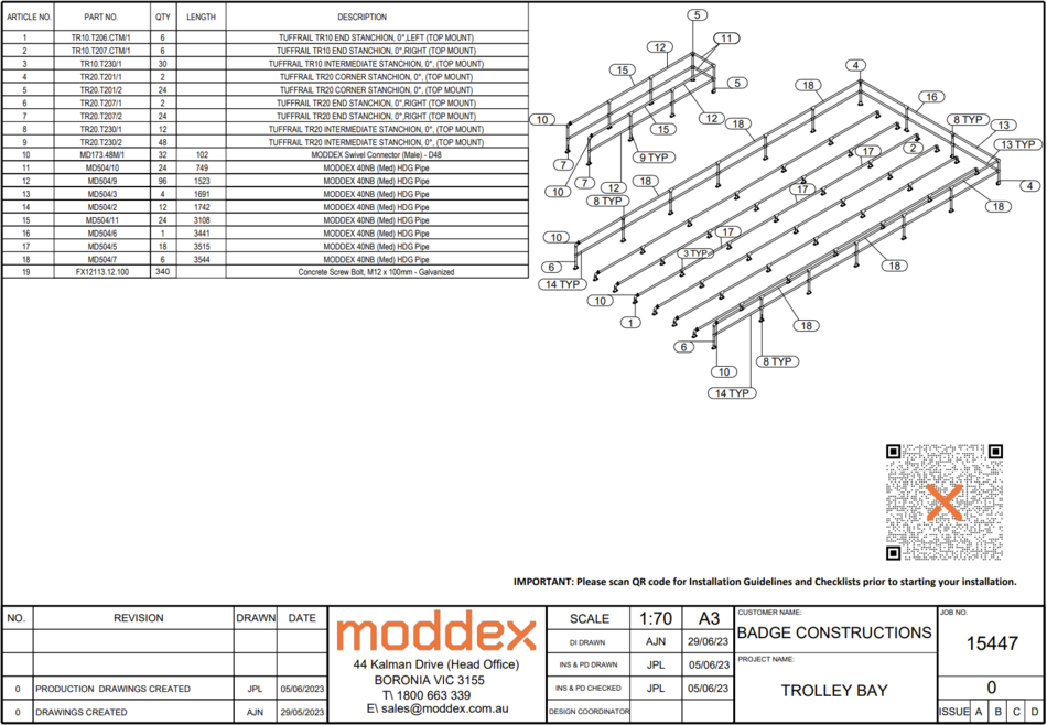
Trolley bays aren't done by CAD drafters too often as they are usually just standard parts that can be sold as a package by the sales team. | |||
When CAD drafters do have to design a trolley bay, this is the layout that should be used. | |||
*Section views that includes overall heights | |||
*Any specific fittings that will be used by the customer | |||
*Clearance between trolley bays | |||
[[File:Trolley Bay 1.PNG|frameless|950px]] | [[File:Trolley Bay 1.PNG|frameless|950px]] | ||
| Line 105: | Line 176: | ||
</div></div> | </div></div> | ||
= | =Fab Panels and Pipes= | ||
<div class="toccolours mw-collapsible" style="width:950px; border:none; background-color:transparent; overflow:auto;"> | <div class="toccolours mw-collapsible" style="width:950px; border:none; background-color:transparent; overflow:auto;"> | ||
<div class="mw-collapsible-content"> | <div class="mw-collapsible-content"> | ||
| Line 117: | Line 188: | ||
<div class="toccolours mw-collapsible" style="width:950px; border:none; background-color:transparent; overflow:auto;"> | <div class="toccolours mw-collapsible" style="width:950px; border:none; background-color:transparent; overflow:auto;"> | ||
<div class="mw-collapsible-content"> | <div class="mw-collapsible-content"> | ||
CONECTABAL STD Bal Panel, Galv - 2000mm, 100mm centres | |||
*950mm vertical centres | |||
*12mm rods | |||
[[File:MD530.2000.100.PNG|frameless|950px]] | [[File:MD530.2000.100.PNG|frameless|950px]] | ||
| Line 122: | Line 197: | ||
</div></div> | </div></div> | ||
=== | ===MD530.2000.100.04=== | ||
<div class="toccolours mw-collapsible" style="width:950px; border:none; background-color:transparent; overflow:auto;"> | |||
<div class="mw-collapsible-content"> | |||
[[File:MD530.2000.100.04.png|frameless|950px]] | |||
</div></div> | |||
===MD531=== | |||
<div class="toccolours mw-collapsible" style="width:950px; border:none; background-color:transparent; overflow:auto;"> | <div class="toccolours mw-collapsible" style="width:950px; border:none; background-color:transparent; overflow:auto;"> | ||
<div class="mw-collapsible-content"> | <div class="mw-collapsible-content"> | ||
In the Master Fittings and Fixings list this part is labelled as MD531, however in Tekla for the part to number it needs to have the assembly number MD531.100 | In the Master Fittings and Fixings list this part is labelled as MD531, however in Tekla for the part to number it needs to have the assembly number MD531.100 | ||
CONECTABAL STD Bal Closure Panel, Galv | |||
*950mm vertical centres | |||
*12mm rods | |||
[[File:MD531.100.PNG|frameless|950px]] | [[File:MD531.100.PNG|frameless|950px]] | ||
| Line 182: | Line 272: | ||
[[File:MD535.2000.100.PNG|frameless|950px]] | [[File:MD535.2000.100.PNG|frameless|950px]] | ||
< | </div></div> | ||
===MD535.2000.100.04=== | |||
<div class="toccolours mw-collapsible" style="width:950px; border:none; background-color:transparent; overflow:auto;"> | |||
<div class="mw-collapsible-content"> | |||
[[File:MD535.2000.100 | [[File:MD535.2000.100.04.png|frameless|950px]] | ||
</div></div> | |||
===MD537.04.D=== | ===MD537.04.D=== | ||
| Line 217: | Line 306: | ||
[[File:MD540.2000.100.PNG|frameless|950px]] | [[File:MD540.2000.100.PNG|frameless|950px]] | ||
</div></div> | |||
===MD540.2000.100.04=== | |||
<div class="toccolours mw-collapsible" style="width:950px; border:none; background-color:transparent; overflow:auto;"> | |||
<div class="mw-collapsible-content"> | |||
[[File:MD540.2000.100.04.png|frameless|950px]] | |||
</div></div> | |||
===MD545.2000.100=== | |||
<div class="toccolours mw-collapsible" style="width:950px; border:none; background-color:transparent; overflow:auto;"> | |||
<div class="mw-collapsible-content"> | |||
[[File:MD545.2000.100.png|frameless|950px]] | |||
</div></div> | |||
===MD545.2000.100.04=== | |||
<div class="toccolours mw-collapsible" style="width:950px; border:none; background-color:transparent; overflow:auto;"> | |||
<div class="mw-collapsible-content"> | |||
[[File:MD545.2000.100.04.png|frameless|950px]] | |||
</div></div> | </div></div> | ||
| Line 225: | Line 338: | ||
[[File:MD550.2000.100.PNG|frameless|950px]] | [[File:MD550.2000.100.PNG|frameless|950px]] | ||
</div></div> | |||
===MD550.2000.100.04=== | |||
<div class="toccolours mw-collapsible" style="width:950px; border:none; background-color:transparent; overflow:auto;"> | |||
<div class="mw-collapsible-content"> | |||
[[File:MD550.2000.100.04.png|frameless|950px]] | |||
</div></div> | </div></div> | ||
| Line 290: | Line 411: | ||
[[File:MD557.04.U.PNG|frameless|950px]] | [[File:MD557.04.U.PNG|frameless|950px]] | ||
</div></div> | |||
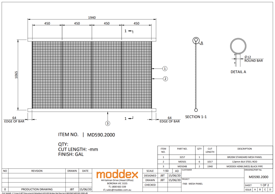
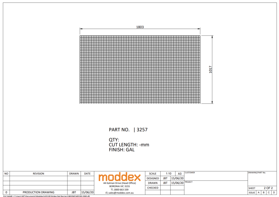
===MD590.2000 (Mesh Panel)=== | |||
<div class="toccolours mw-collapsible" style="width:950px; border:none; background-color:transparent; overflow:auto;"> | |||
<div class="mw-collapsible-content"> | |||
[[File:590.2000.1.PNG|frameless|950px]] | |||
[[File:590.200.2.PNG|frameless|950px]] | |||
</div></div> | </div></div> | ||
===BAL.ASM.CTM=== | ===BAL.ASM.CTM=== | ||
| Line 303: | Line 434: | ||
</div></div> | </div></div> | ||
| Line 312: | Line 442: | ||
===90 Degree Panel=== | ===90 Degree Panel=== | ||
[[File:90 | [[File:BAL.90.01.png|frameless|950px]] | ||
===90 Degree Rounded Panel=== | ===90 Degree Rounded Panel=== | ||
[[File:90 | [[File:BAL.90.02.png|frameless|950px]] | ||
===180 Degree Flat Panel=== | ===180 Degree Flat Panel=== | ||
[[ | [[FILE:BAL.90.03.png|frameless|950px]] | ||
===Angled Panel=== | ===Angled Panel=== | ||
[[ | [[FILE:BAL.30.01.png|frameless|950px]] | ||
===Straight Transition Panel=== | ===Straight Transition Panel=== | ||
[[File: | [[File:BAL.TP.01.png|frameless|950px]] | ||
===Mitered Closure Panel=== | ===Mitered Closure Panel=== | ||
[[File: | [[File:BAL.EP.03.png|frameless|950px]] | ||
===Closure Panel Angled=== | ===Closure Panel Angled=== | ||
[[File:Closure Panel Angled.PNG|frameless|950px]] | [[File:Closure Panel Angled.PNG|frameless|950px]] | ||
===MD580.2000.100 BridgeRail=== | ===MD580.2000.100 BridgeRail=== | ||
| Line 345: | Line 470: | ||
===Skate Ramp Rolled Balustrade Panel=== | ===Skate Ramp Rolled Balustrade Panel=== | ||
[[File: | [[File:BAL.RP.01.png|frameless|950px]] | ||
[[File: | |||
===Rolled Balustrade Panel=== | |||
[[File:BAL.RP.02.png|frameless|950px]] | |||
===BAL.EP.01=== | |||
<div class="toccolours mw-collapsible" style="width:950px; border:none; background-color:transparent; overflow:auto;"> | |||
<div class="mw-collapsible-content"> | |||
[[File:BAL.EP.01.png|frameless|950px]] | |||
</div></div> | |||
===BAL.EP.02=== | |||
<div class="toccolours mw-collapsible" style="width:950px; border:none; background-color:transparent; overflow:auto;"> | |||
<div class="mw-collapsible-content"> | |||
[[File:BAL.EP.02.png|frameless|950px]] | |||
</div></div> | |||
===BAL.EP.03=== | |||
<div class="toccolours mw-collapsible" style="width:950px; border:none; background-color:transparent; overflow:auto;"> | |||
<div class="mw-collapsible-content"> | |||
[[File:BAL.EP.03.png|frameless|950px]] | |||
</div></div> | |||
==Standard Pipe Parts== | ==Standard Pipe Parts== | ||
| Line 384: | Line 536: | ||
==Gate Drawings== | ==Gate Drawings== | ||
===MD582PC=== | |||
[[File:MD582PC.PNG|frameless|950px]] | [[File:MD582PC.PNG|frameless|950px]] | ||
Note: On aluminium gates the current gate tool spawns in MD365's, the correct code is MD365M. | |||
===A-Frame with Cow Latch=== | |||
====For any A-Frame gates (ALY or HDG) please supply an extra 3031 gate hinge to give it more support. We’ll just draw them with 3 hinges but as the hinges come in pairs they’ll have 4 if required==== | |||
[[File:A Frame 1.PNG|frameless|950px]] | |||
[[File:A Frame 2.PNG|frameless|950px]] | |||
[[File:A Frame 3.PNG|frameless|950px]] | |||
[[File:A Frame 4.PNG|frameless|950px]] | |||
[[File:A Frame 5.PNG|frameless|950px]] | |||
==Bent Pipe Multidrawings== | ==Bent Pipe Multidrawings== | ||
| Line 421: | Line 588: | ||
[[File:Welded Stanchion PD.PNG|frameless|950px]] | [[File:Welded Stanchion PD.PNG|frameless|950px]] | ||
</div></div> | </div></div> | ||
==Rolled Kickplate== | |||
[[File:Rolled Kickplate.PNG|frameless|950px]] | |||
=Baseplates= | =Baseplates= | ||
Latest revision as of 04:50, 11 December 2025
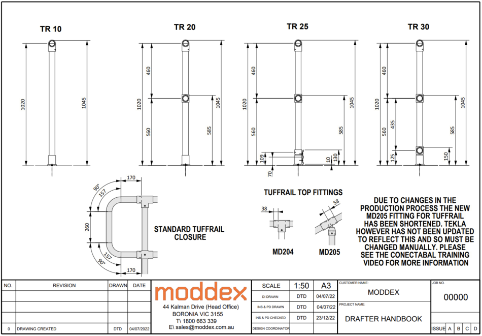
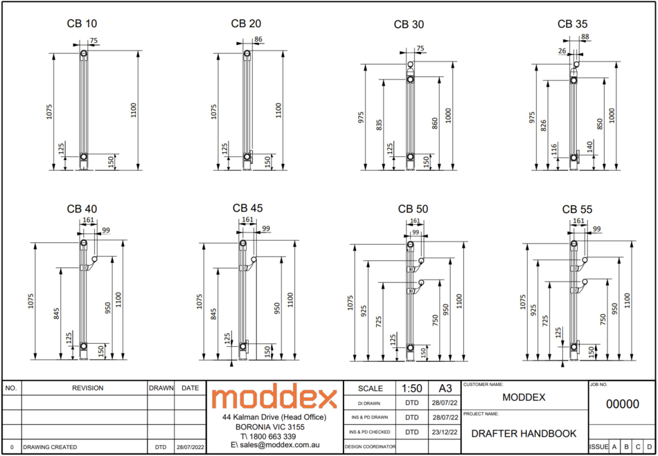
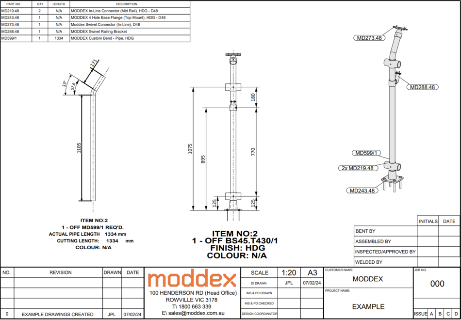
On this page are examples of all different types of drawings to be referenced when creating DI, PDs, FABs, and INS.
To add an example drawing
Send a screenshot of the drawing to a DC and after they review it, the drawing can be added to this list.
Document Manager Layout
In the document manager there are certain ways drawings are named in the title 1 column.
- Design Intent - DI
- Production Drawings - PD
- Installation Drawings - ID
- Fabrication Drawings - FD
- Rolled Drawings - RD
These are titled by 'Prefix' 'number'
For example a PD title page would be titled "PD 0". This is so that the first stanchion will be titled "PD 1".
These prefix's are added so that any drafter can load into a model and sort by title 1 and the drawings will be listed accordingly.
Basic Drawing Layout Guide
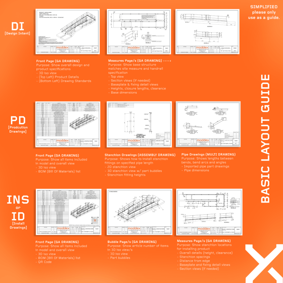
Here is the basic drawing layout guide which can help new drafters understand DI's, PD's, and INS drawings.
General Arrangement
A general arrangement drawing, or GA drawing, is a type of drawing that shows the overall layout and dimensions of a structure or object, such as a building, a bridge, or a machine. It shows how the different parts and components fit together and where they are located. GA drawings are used to plan, design, and construct projects, and to communicate the design to other people involved in the project, such as engineers, architects, and contractors.
GA drawings usually include different views of the structure or object, such as plans (top view), sections (cut view), and elevations (side view). These views are drawn to scale and show the exact measurements and orientations of the parts and components.
GA drawings may also include pictorial views, such as isometric drawings, which show the structure or object in three dimensions. These views are not drawn to scale, but they help to visualize the overall shape and appearance of the structure or object.
Reference Models
When using a reference model for a design intent, remember to include a note on all DI drawings that the reference model:" " has been used.
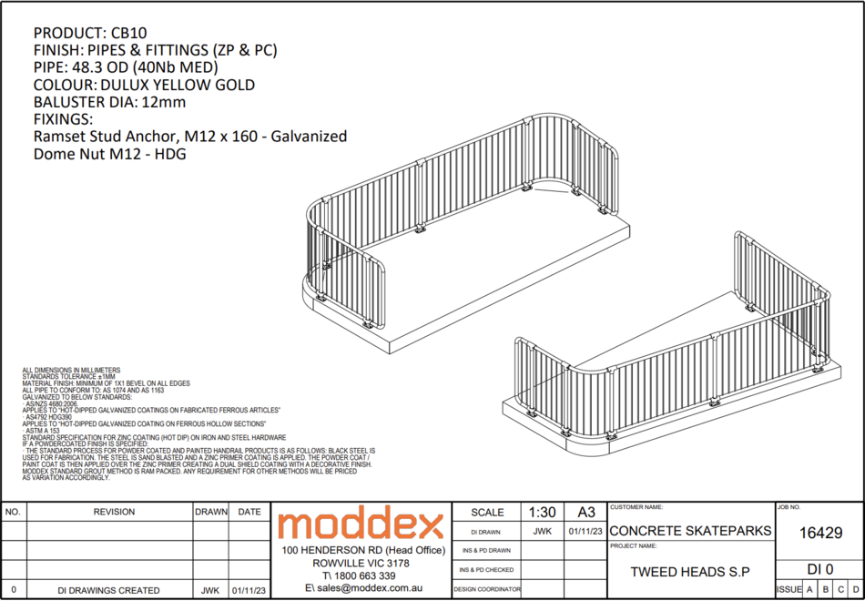
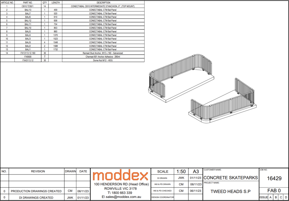
Title Page
Design Intent
Production/Fabrication/Rolled Drawings
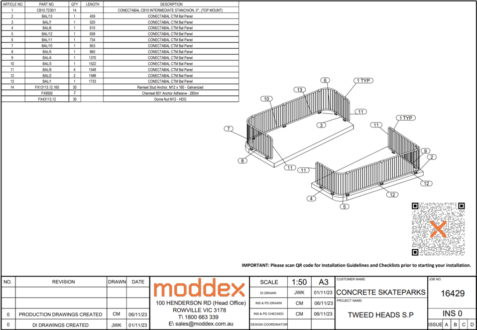
Install Drawings
Install title pages should include
- An overall isometric view of the model
- BOM list
- Installation QR code
- Customer name
- Project name
- Job number
- Any required revision notes
- Initials
- Dates
Note: Install drawing title pages only need bubbles if the BOM is small enough to fit all part bubbles in the title page.
If the title looks too busy, remove the bubbles and give them separate pages.
Disability Ramp
Small Stair
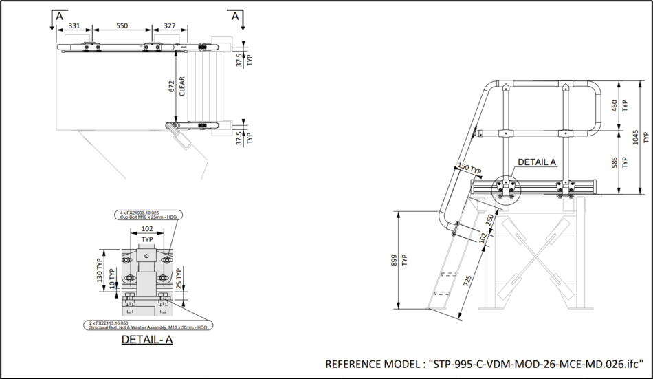
This is the general layout of a small staircase.
Couple of things to note:
- Measurements show the angle, nosing to nosing, rise, and run lengths
- Measurements showing how far both bottom landing and top landing closures stick out
On more simpler designs, try to show more information to fill out the page.
There is a lot of space to fill, so show the customer a bit more information than what's just necessary.
Mezzanine
Fire Stairs
Fire stairs are staircases that are designed for emergency use in case of a fire or other disaster. They provide a safe and quick way to exit a building and prevent the spread of fire. Fire stairs are usually isolated from the rest of the building by fire-resistant walls and doors.
It is important to show all measurements in a general arrangement drawing of fire stairs because they help to ensure that the fire stairs are built according to the design and safety requirements. Accurate measurements help to avoid errors, save time and money, and ensure quality and accuracy. They also help to communicate the design to other people involved in the project, such as engineers, architects, and contractors.
When creating GA drawings for fire stairs, an isometric view of the section should be shown before the section view of the stairs themselves to help enhance the understanding and communication of the design.
Trolley Bay
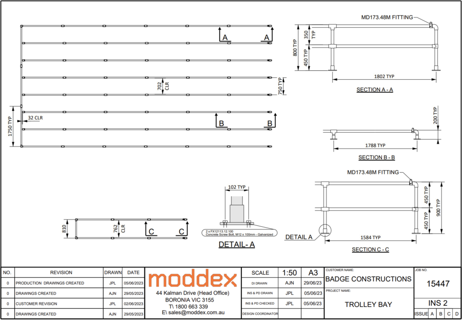
Trolley bays aren't done by CAD drafters too often as they are usually just standard parts that can be sold as a package by the sales team.
When CAD drafters do have to design a trolley bay, this is the layout that should be used.
- Section views that includes overall heights
- Any specific fittings that will be used by the customer
- Clearance between trolley bays
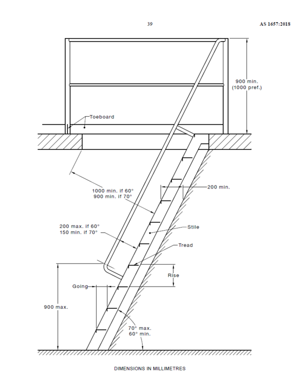
Ladder
Ladders are designed to follow AS1657.
Fab Panels and Pipes
CB Standard Parts
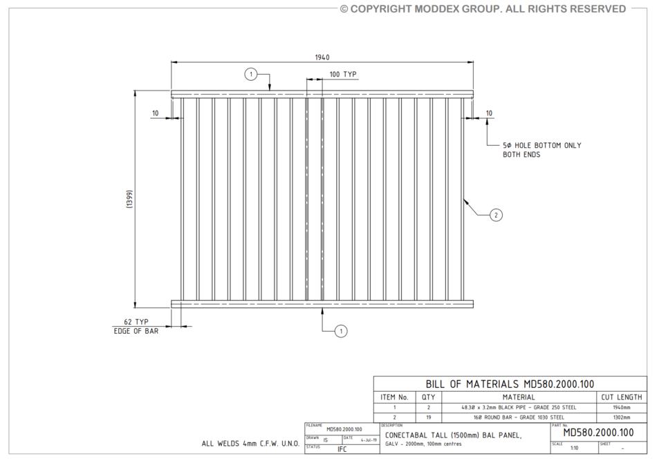
MD530.2000.100
MD530.2000.100.04
MD531
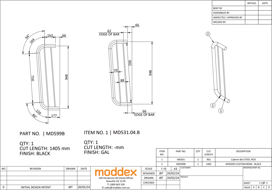
MD531.04.B
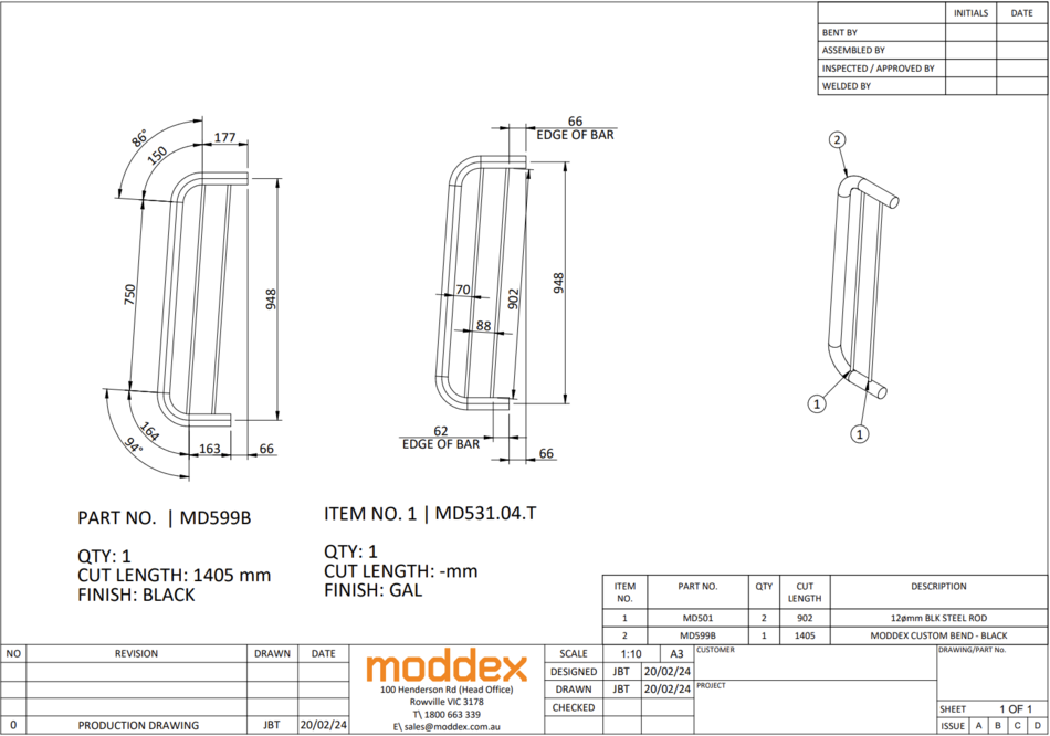
MD531.04.T
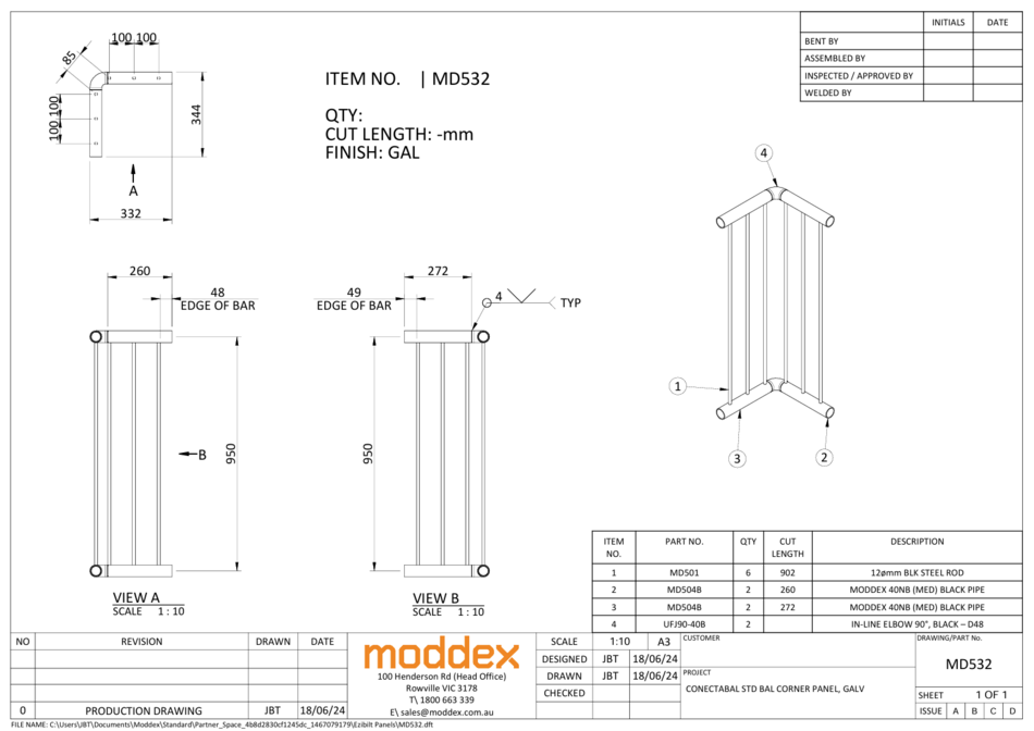
MD532
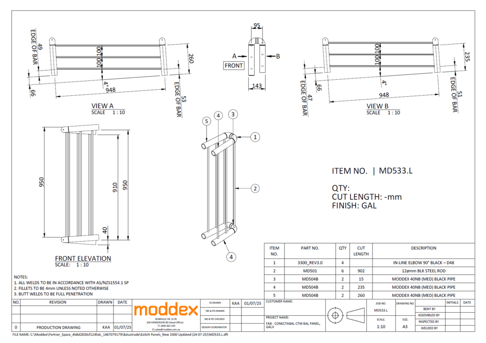
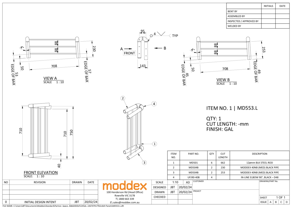
MD533.L
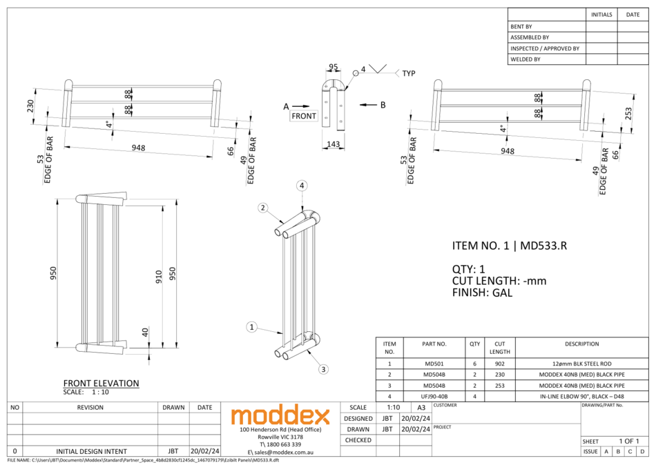
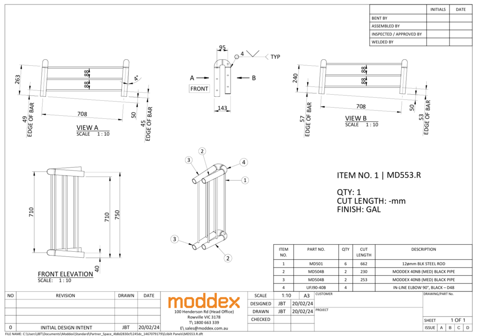
MD533.R
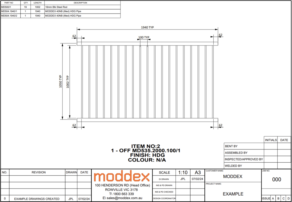
MD535.2000.100
MD535.2000.100.04
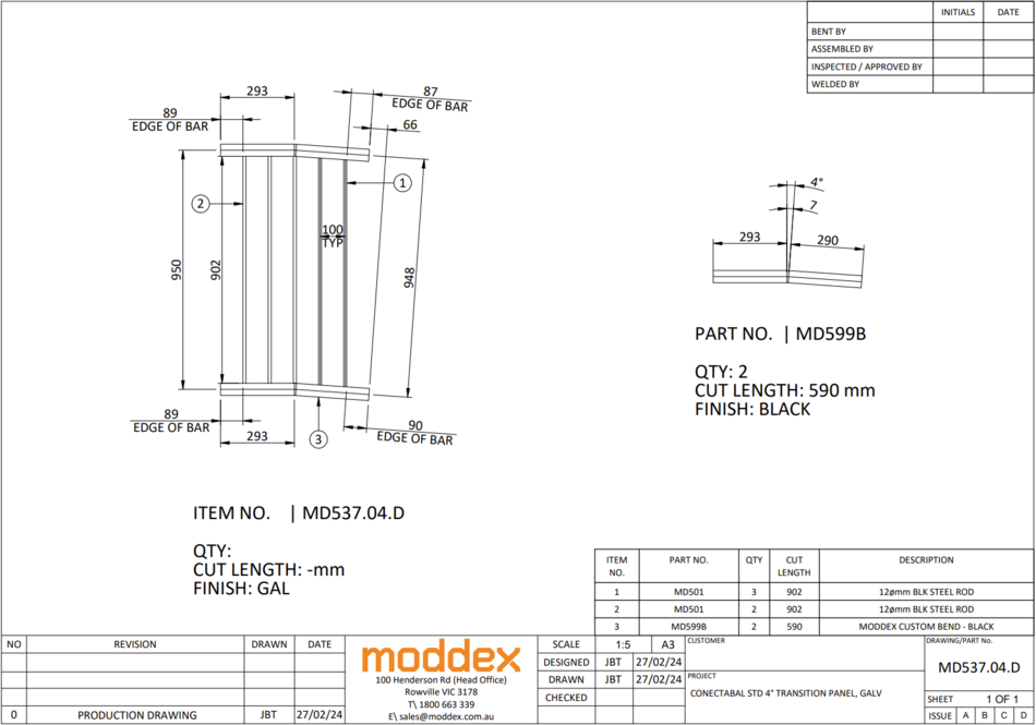
MD537.04.D
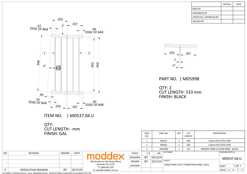
MD537.04.U
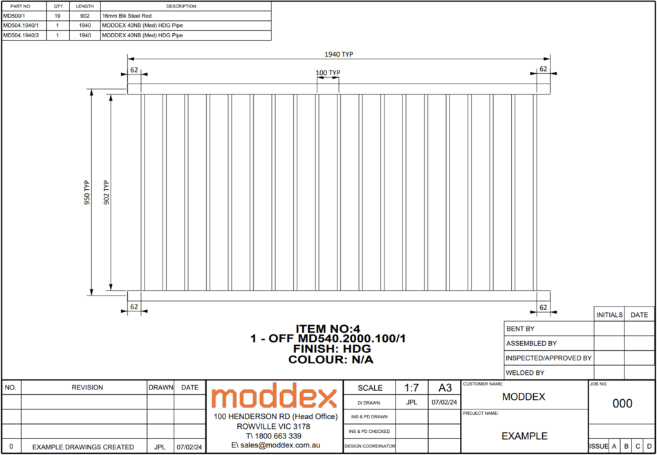
MD540.2000.100
MD540.2000.100.04
MD545.2000.100
MD545.2000.100.04
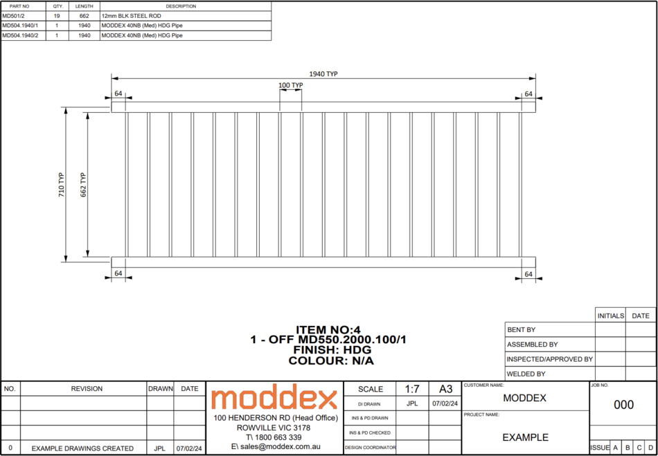
MD550.2000.100
MD550.2000.100.04
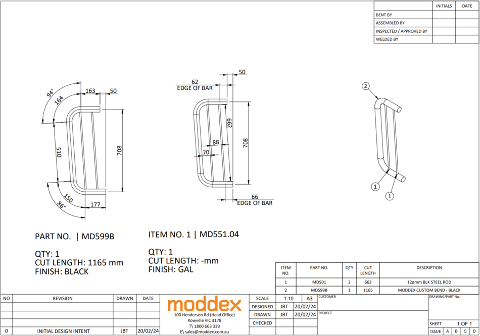
MD551.04
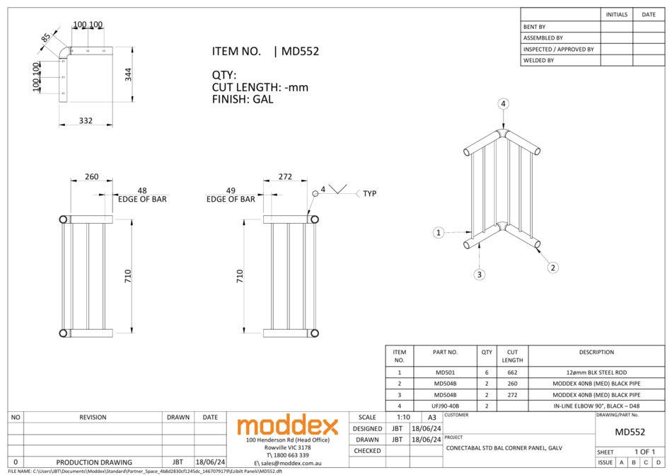
MD552
MD553.L
MD553.R
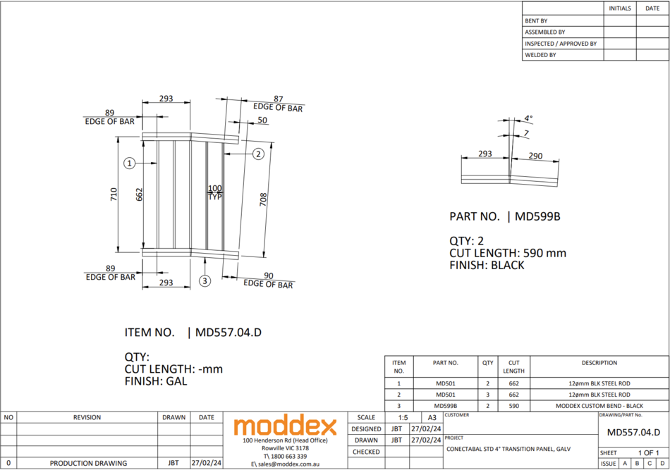
MD557.04.D
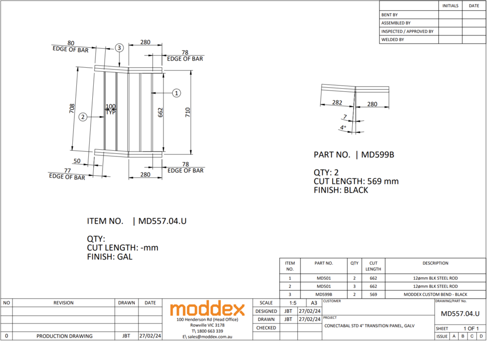
MD557.04.U
MD590.2000 (Mesh Panel)
BAL.ASM.CTM
CB Fabricated
Skate Ramp Rolled Balustrade Panel
Rolled Balustrade Panel
BAL.EP.01
BAL.EP.02
BAL.EP.03
Standard Pipe Parts
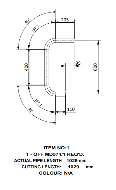
MD574 - BS Closure
BIKESAFE Closure Bend
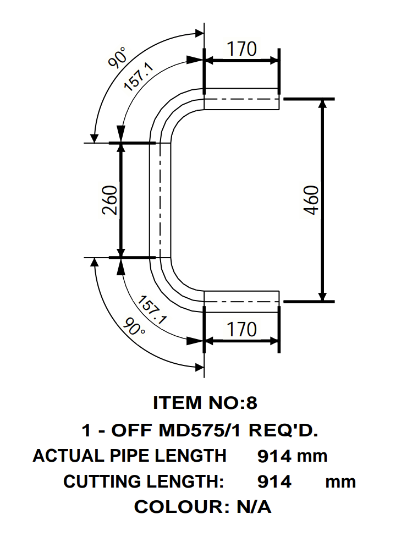
MD575 - TR Closure
TUFFRAIL Closure Bend, Horizontal - D48
MD578
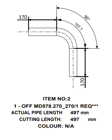
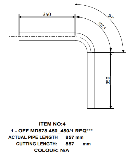
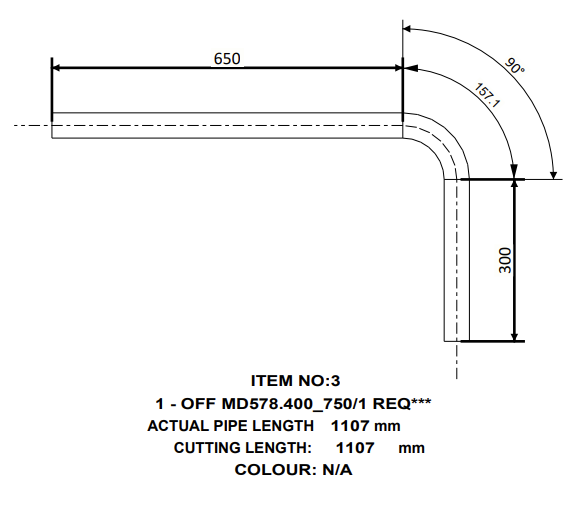
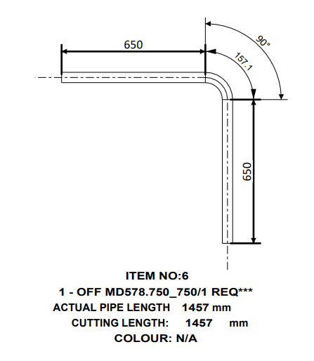
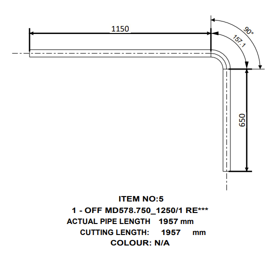
The only MD578 that are stocked and used by CAD is MD270_270 for TR corners. All other MD578 sizes are not stocked, however sales can still use them as standard parts for CAT 1 BOM jobs.
MD578.270_270
MD578.450_450
MD578.400_750
MD578.750_750
MD578.750_1250
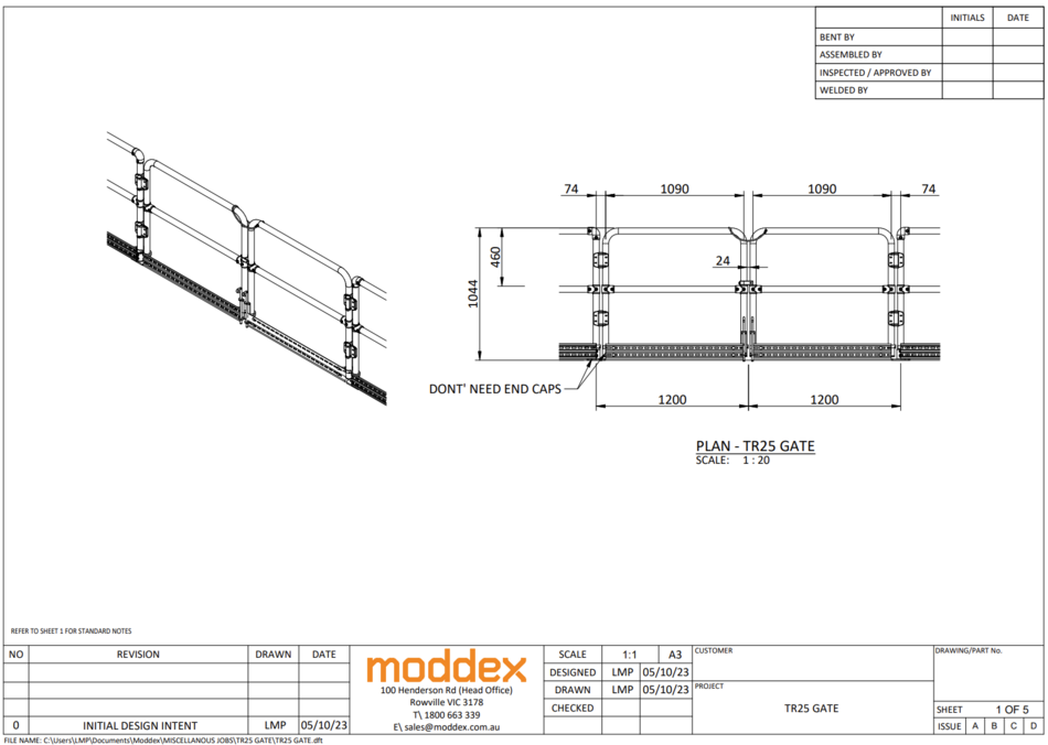
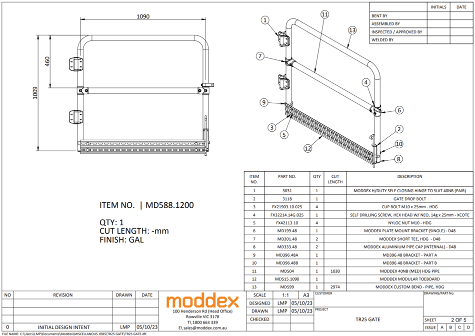
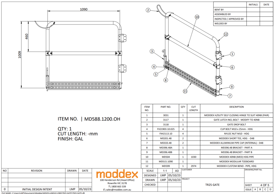
Gate Drawings
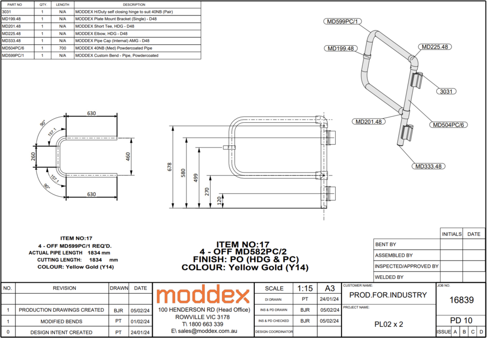
MD582PC
Note: On aluminium gates the current gate tool spawns in MD365's, the correct code is MD365M.
A-Frame with Cow Latch
For any A-Frame gates (ALY or HDG) please supply an extra 3031 gate hinge to give it more support. We’ll just draw them with 3 hinges but as the hinges come in pairs they’ll have 4 if required
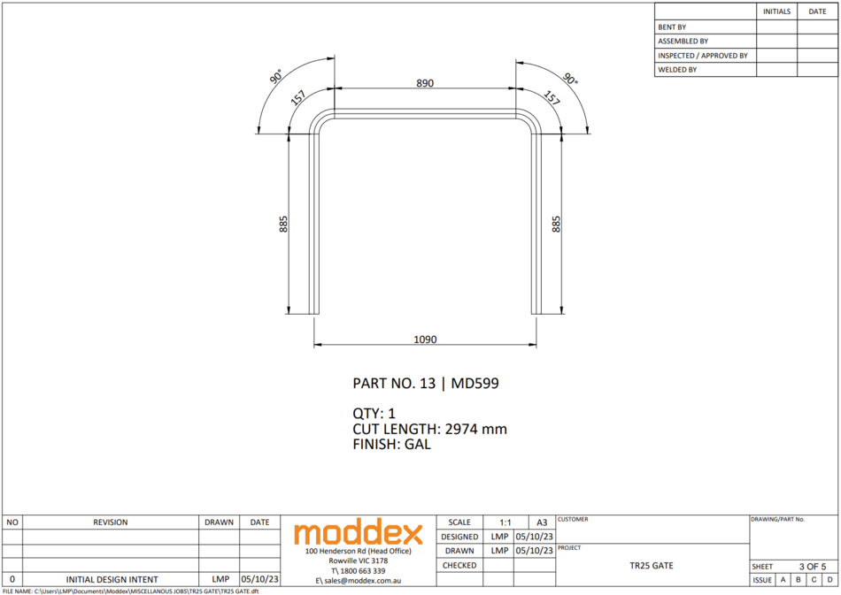
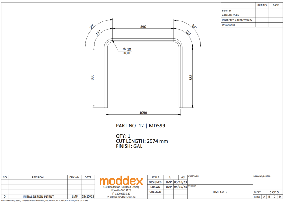
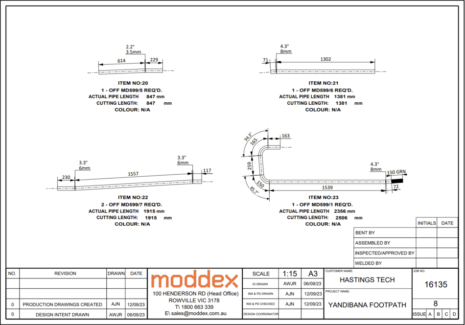
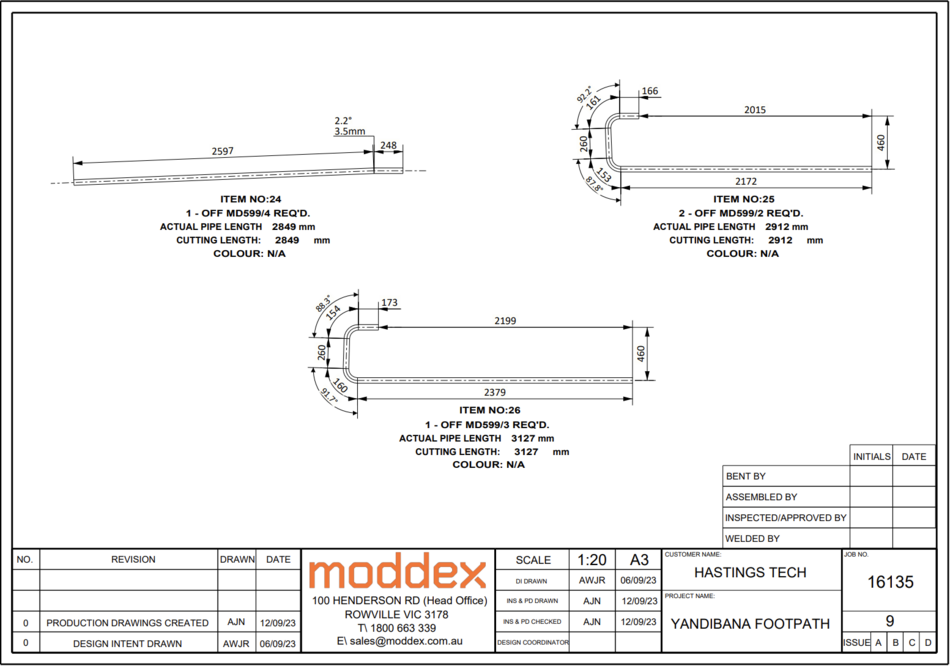
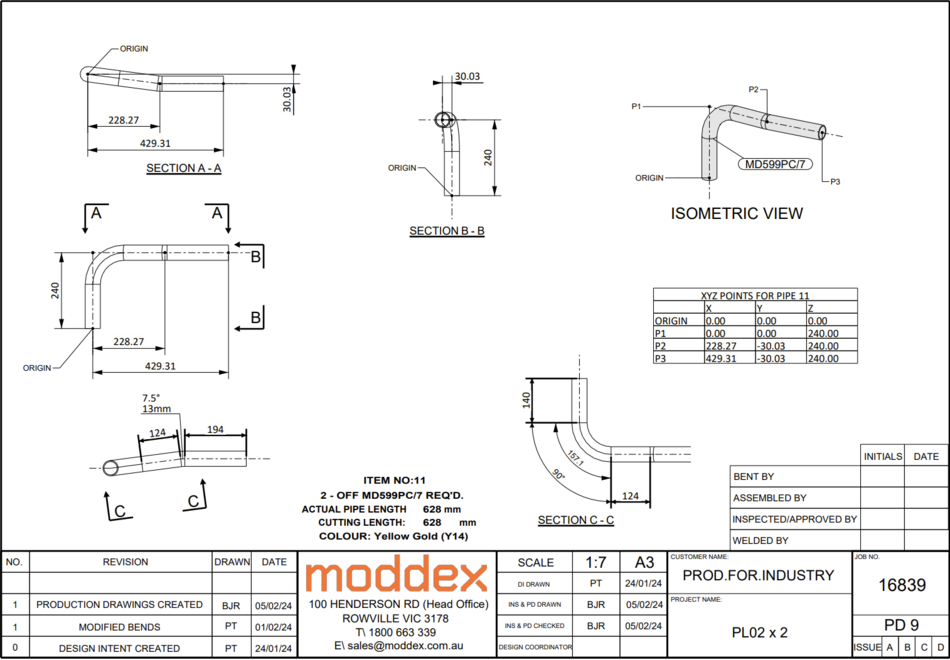
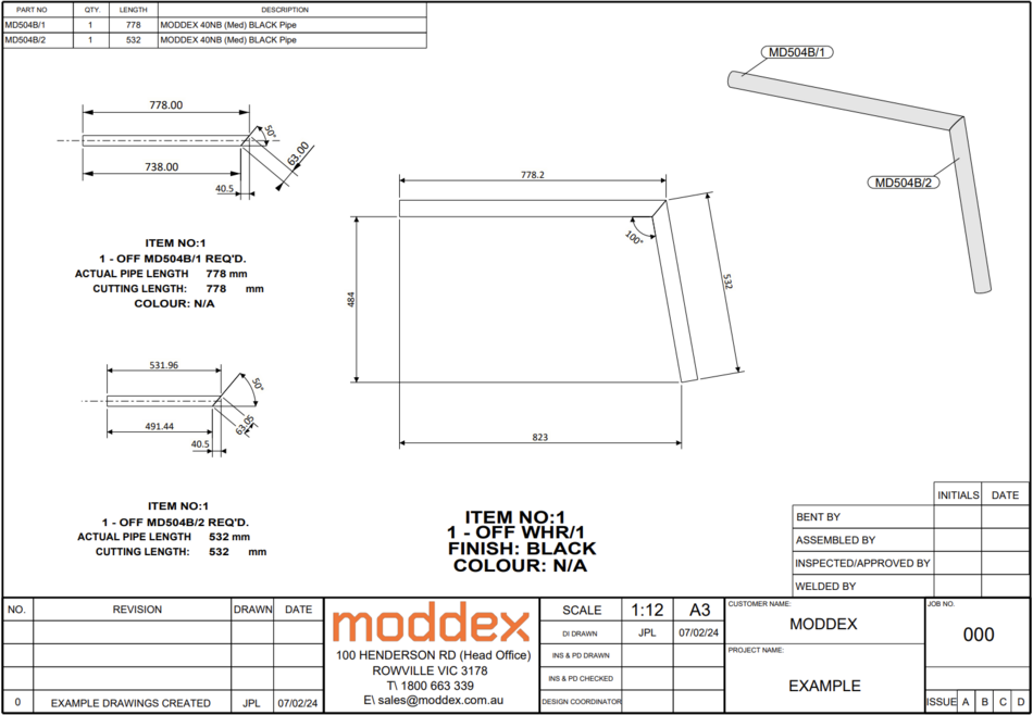
Bent Pipe Multidrawings
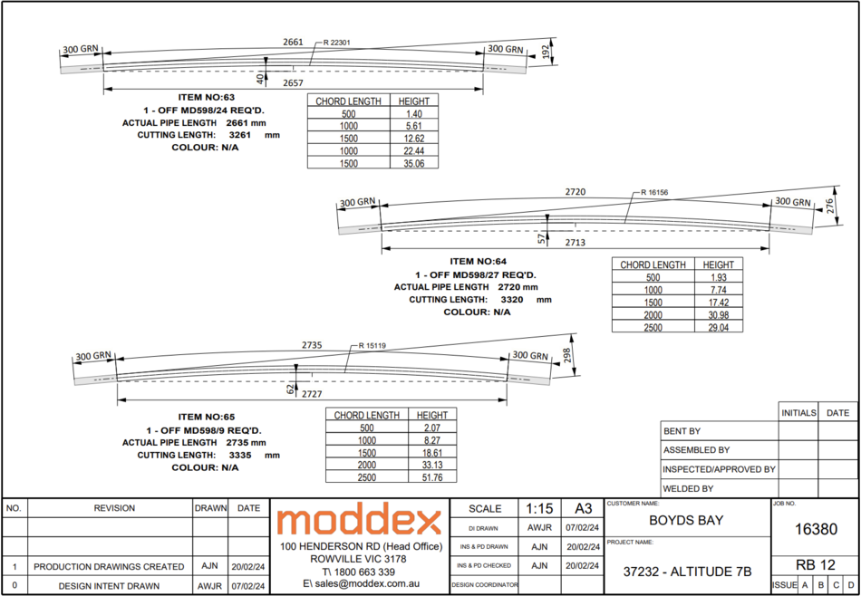
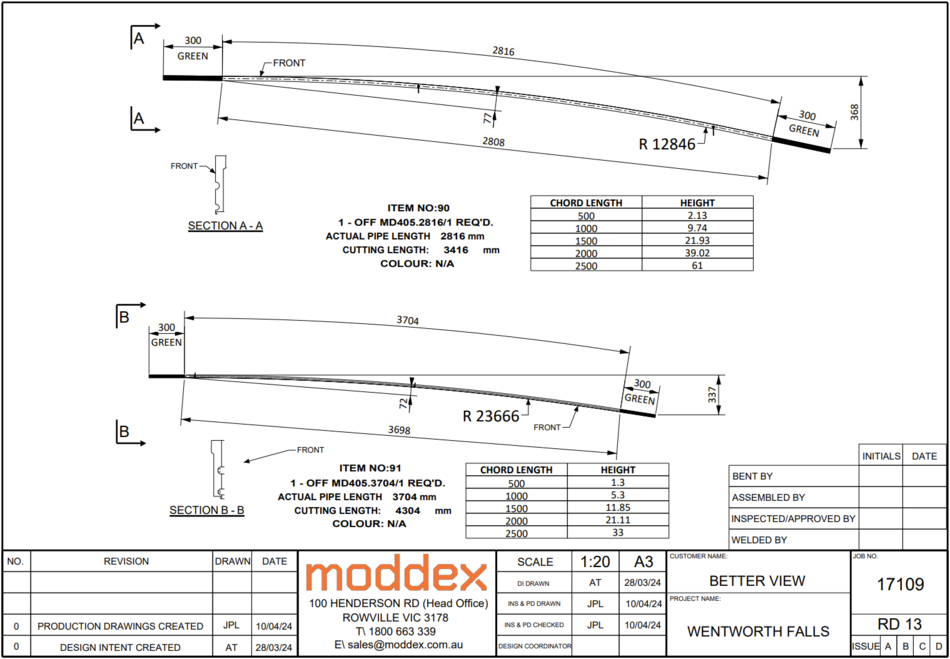
Rolled Pipe Multidrawings
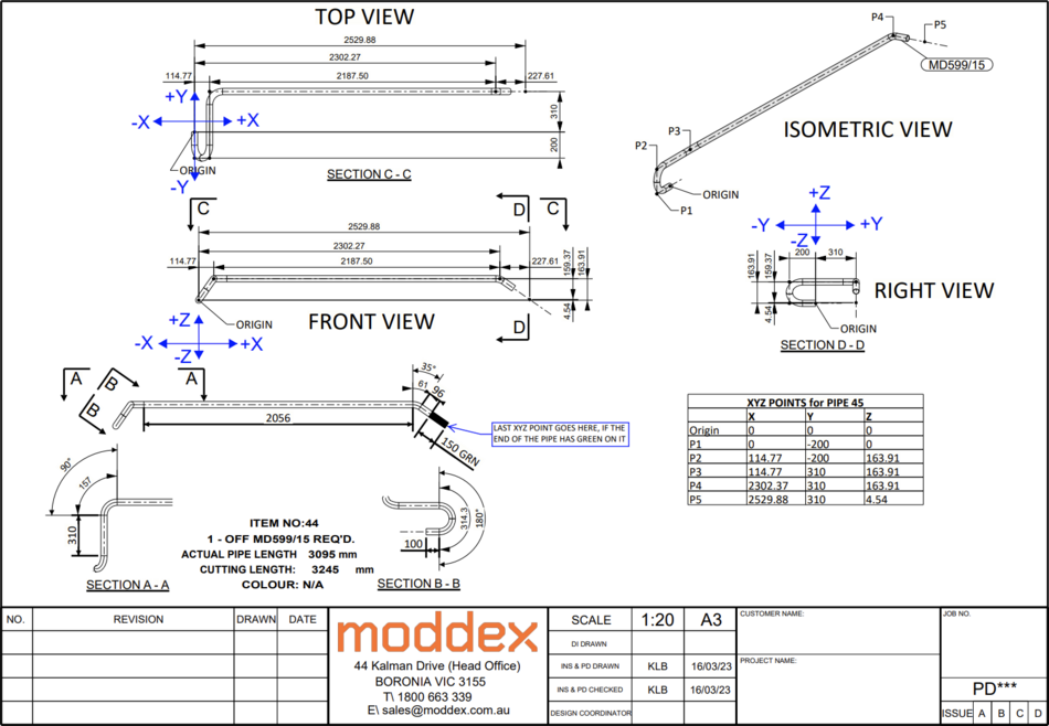
XYZ Drawings
If you need any help creating these drawings, click the hyperlink to view the XYZ video tutorial
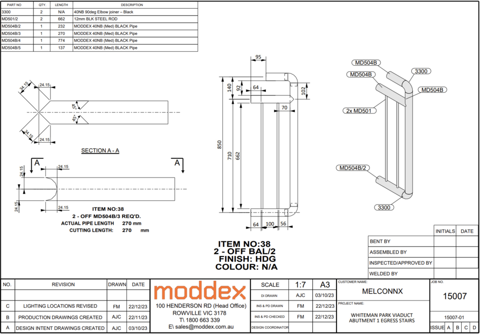
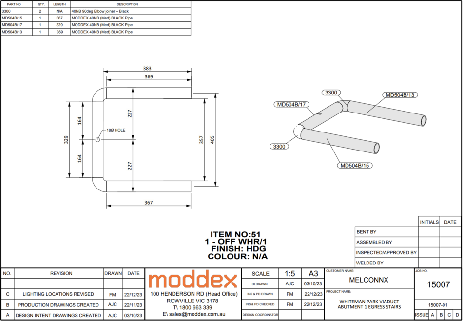
Mitered Handrail
Welded Handrail
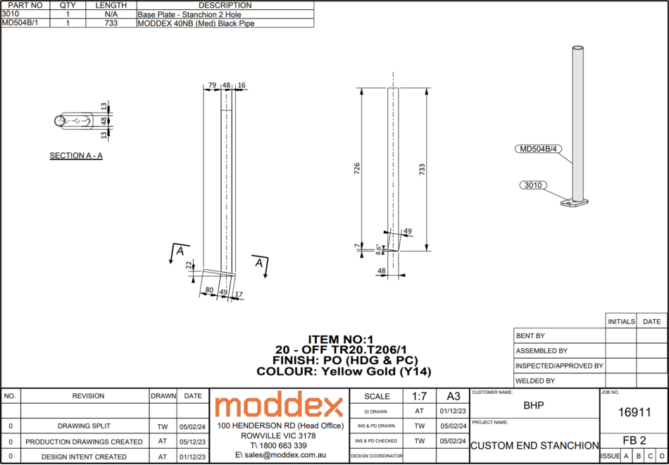
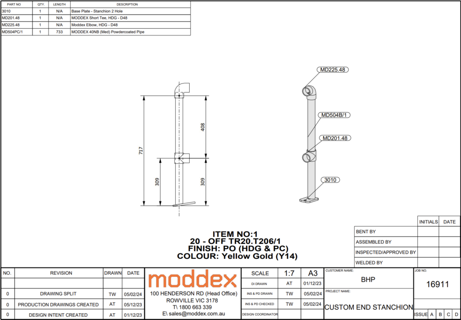
Welded Stanchions
Rolled Kickplate
Baseplates
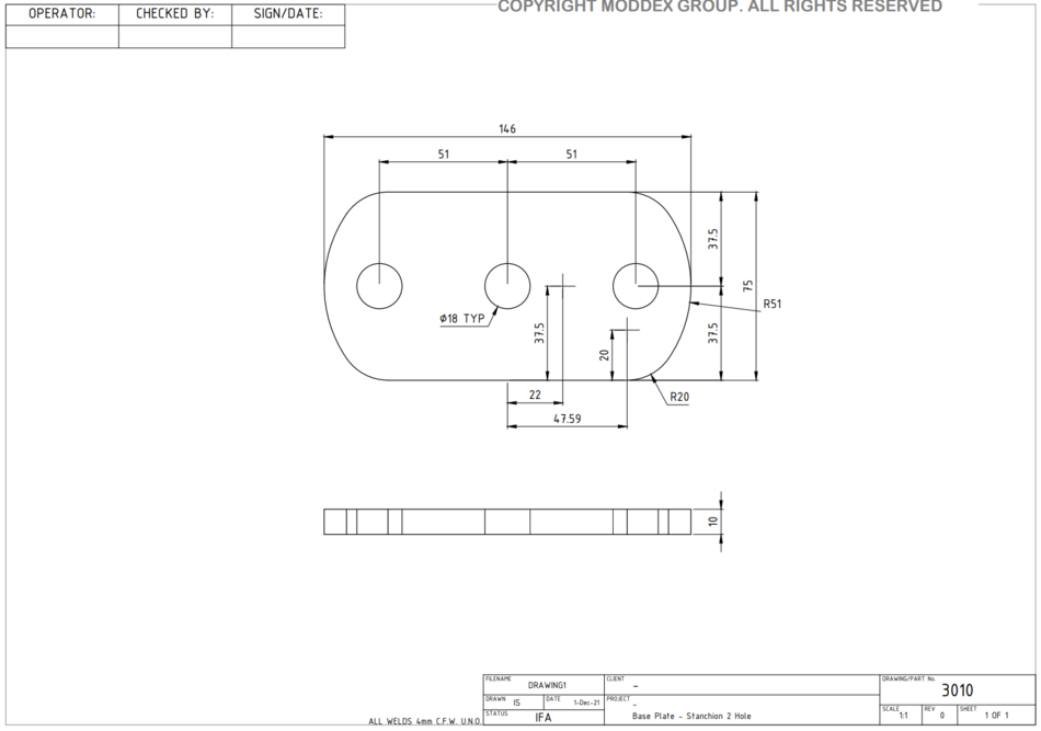
3010
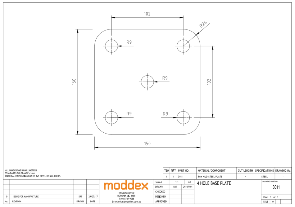
3011
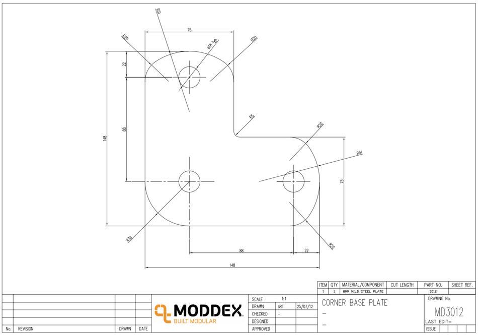
3012
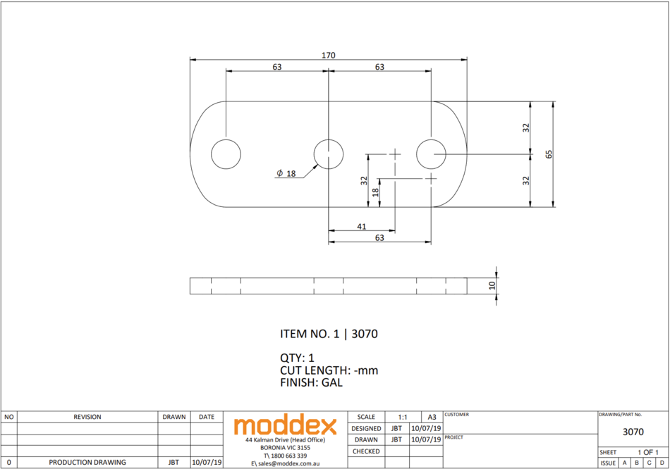
3070
2 hole baseplate, 126mm
- When using any CB product on a stair stringer, we either need to use a 3070 welded baseplate or bend the stanchion pipe and use a MD232.
- When mounting to pre-drilled holes, the 3070 needs to be used, but any other time a bent post can be used.
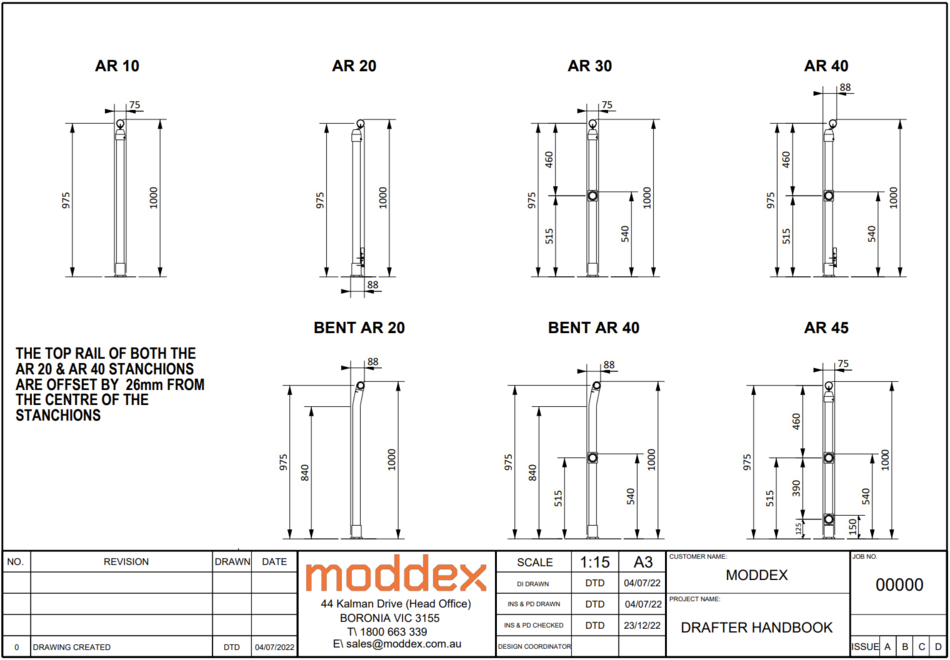
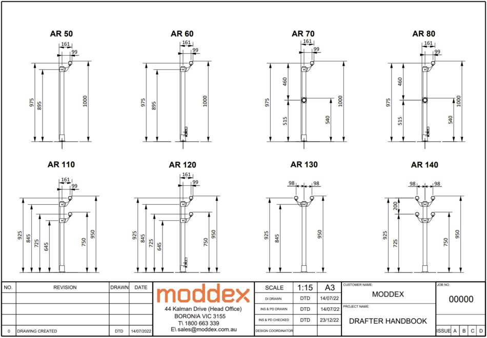
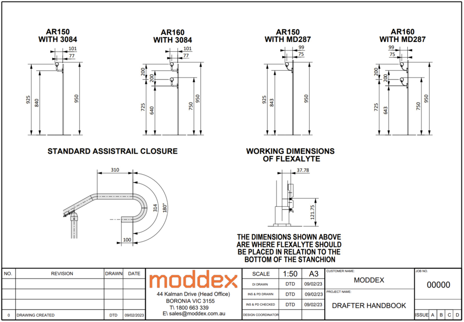
Stanchions
AssistRail
TuffRail
Conectabal

